Positional tolerance is a type of geometric tolerance that is used to determine the permissible range of changes in the position of a feature of the part.
This type of tolerance is especially important for easy and trouble-free assembly of various parts in the industry.
In this article, we are going to examine the concept and how to measure this tolerance in the industry.
We invite you to stay with us until the end of this article.
1# What is position tolerance? ( Position Tolerance )
True Position is , which of course is the name of one of the types of geometric tolerances as position tolerance . better known
This tolerancing method is included in the subcategory of the location tolerance group.
This tolerance is used to determine the exact position of a feature relative to one or more bases in engineering drawings.
In other words, it specifies the maximum allowed deviation of a feature such as a hole in the manufacturing process from its actual position on the map.
When it comes to positioning, we will need a base or reference for this purpose.
Basically, in engineering drawings, position tolerance is done by specifying planes and axes as bases.
This tolerance can be defined in two-dimensional or three-dimensional engineering drawings and is widely used in the industry.
Take a car engine as an example.
Screws are used to connect the cylinder head gasket to the engine body.

For this reason, it is necessary that the holes on the cylinder head gasket and the engine body match each other in terms of size and position.
Otherwise, even if the bolts are tightened, the cylinder head gasket may not sit well on the engine body.
As you know, the role of the cylinder head gasket is to seal the engine.
The misalignment of the holes relative to each other will cause water and oil leaks in the engine.
As a result, engine parts are damaged very quickly.
We used this relatively simple example to show how important it is to consider the position error in the process of manufacturing and assembling various parts.
2# The difference between position tolerance and dimensional tolerance
compared to dimensional tolerance . The use of position tolerance increases the permissible error range
For this reason, the production of parts is easier and faster and the cost of production is reduced.
Why does this happen?
Suppose we want to determine the position of the center of a hole on a part with the help of dimensional tolerance.
We place the center of the coordinate axis on the actual position of the hole on the map.
Then we define the permissible error zone at a distance of 0.25 mm from the horizontal axis and 0.25 mm from the vertical axis.
With a thumb calculation, it is determined that the maximum distance from the actual position at the time of manufacture is 0.35 mm (diameter of the created square).
In addition, the square area that we considered for the permissible error will be equal to 0.25 mm square.
Now we are going to calculate the permissible error range using position tolerance.
In this method, we consider a circle with a radius of 0.5 mm compared to the actual position of the hole for deviation.
When you add the two 0.25mm dimensional tolerance errors together, you get 0.5mm.
On paper, these two tolerances appear to specify the same allowable range for the hole; But the story is completely different.
In positioning tolerance, instead of drawing a square, they use a circle to determine the permissible error range;
So you consider a circle with a radius of 0.5 mm to deviate the position of the hole.
A thumb calculation shows that the area of the circle is 0.785 mm2.
As you can see, the area of a circle is much larger than a square.
For this reason, the permissible error range for the production of parts will increase.
3# How to define the real situation
As you can see, the use of positional tolerance helps to increase the margin of error by more than 30% compared to dimensional tolerance.
This issue has caused a lot of emphasis on this tolerance method in the GD&T standard language.
In addition, experience has shown that the use of this method prevents confusion in setting tolerances.
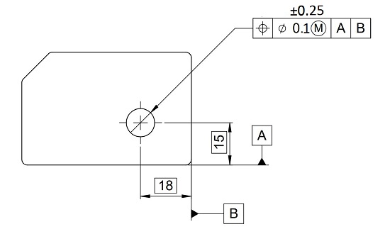
You can see the symbol of this tolerance in the first house from the left side of the feature control frame of the image below.
Next, the numerical value of the tolerance is determined in the second house of the feature control framework.
This value indicates the diameter of the circle of the permissible range of error in the design of parts.
In addition, as we mentioned, there is a need to determine the axis or plane as a basis for defining this tolerance.
Usually, in the third house of the feature control frame, the geometric bases are determined on the map.
In the above image, two sides A and B of the part are selected as the basis.
That is, the basis for measuring and determining tolerance is based on these two sides.
In this way, the tolerance can be fully specified for a feature in the drawing.